Applications
Table of contents:
Understanding the theory of LESS
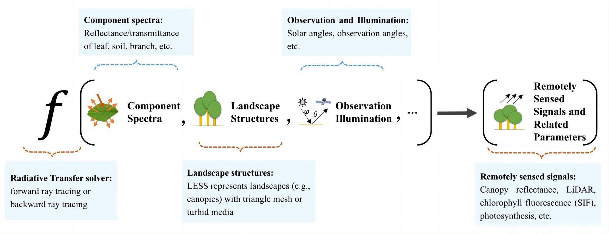
The aim of LESS is to simulate the radiation interactions within intricate landscapes, such as forests and urban structures. The following two figures succinctly outline the primary functionalities of LESS. By inputting landscape structural data, component spectra, illumination/observation geometries, and other necessary information, LESS utilizes ray tracing techniques to solve the 3D radiative transfer problem. It then generates remotely sensed signals, encompassing canopy reflectance, LiDAR data, multispectral images, Solar-Induced Fluorescence (SIF), as well as various process parameters like Fraction of Photosynthetically Active Radiation (FPAR) and photosynthesis rates.
This process is often referred to as “forward simulation or modeling”. Unlike other 1D models, LESS does not rely on assumptions that abstract the canopy as homogeneous layers. Instead, it employs explicitly described structures to represent landscape elements, even down to the detailed structures of individual leaves or shoots. Consequently, LESS is renowned for its precision. Since the ray tracing technique utilized by LESS simulates light scattering at each ray-object intersection point based on fundamental physical laws (e.g., Lambertian reflection), simulations conducted by models like LESS are sometimes termed “first principle” simulations.
In summary, LESS yields considerably accurate results for light scattering within complex landscapes, facilitating various applications such as forest parameter retrieval, comprehension of remote sensing mechanisms, and sensor instrument design.
-
Light scattering within a forest canopy:
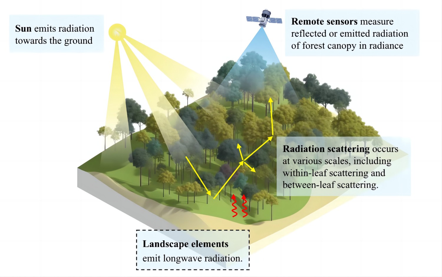
-
The diagram of LESS’s functionality:
Why LESS is useful ?
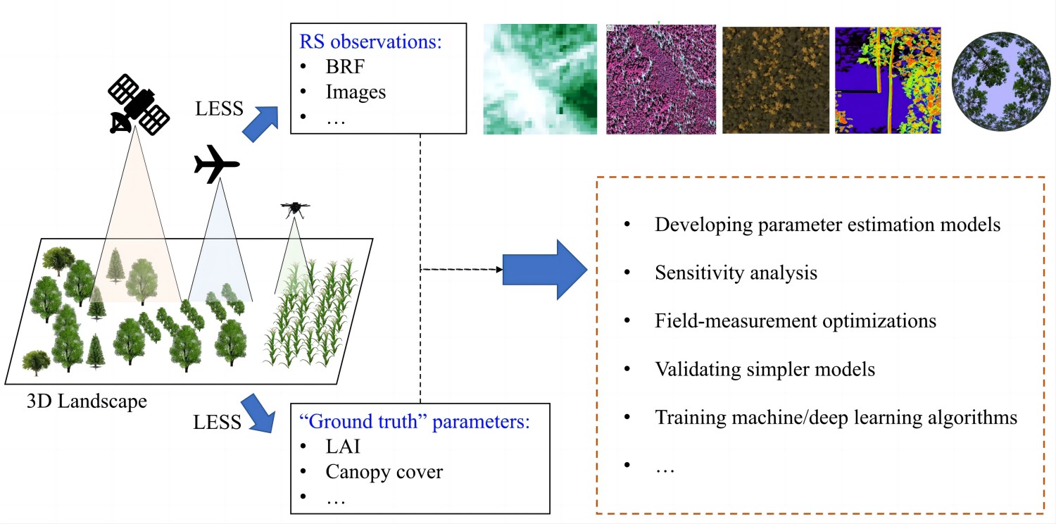
LESS facilitates the aforementioned applications by providing remote sensing observations alongside corresponding “ground truth” measurements. For instance, consider the retrieval of vegetation parameters from canopy reflectance, a fundamental goal in forest remote sensing. To establish a retrieval model, it is imperative to understand the relationship between reflectance and vegetation parameters. While field measurements can offer such insights, they are often laborious and site-specific. Alternatively, employing 3D simulations with LESS serves as an economical alternative. By utilizing the simulated reflectance alongside the ground truth parameters provided by LESS (refer to the figure below), we can establish a regression model or machine learning algorithm. Subsequently, real remote sensing reflectance can be inputted into this model to estimate vegetation parameters. Finally, field measurements can be utilized to validate the accuracy of the model.
- LESS provides remote sensing observations and the corresponding “ground truth” measurements:
Selected applications
1. Simulating FPAR of maize field with different growing stages.
This application employs LESS to analyze the total Fraction of Absorbed Photosynthetically Active Radiation (FPAR) across various growth stages of a maize field. The three-dimensional models of the maize are constructed using the ‘MaizeGenerator’ plugin, which can be found under the ‘Tools’ and ‘LESS Plugins’ sections.
The photon tracing sensor is utilized to simulate the three-dimensional distribution of Photosynthetically Active Radiation (PAR). The total FPAR is then calculated as the cumulative value of all the PAR absorbed by each leaf.
2. Simulating incident/leaving flux of a surface within a scene
This application puts a virtual plane at different heights within the scene, and by using photon tracing module of LESS, It can record the incident flux and outgoing flux of the surface. If the surface is descrbied with tirangle mesh, this module can also records the flux for each triangle. This is particularly useful when you want know how much energy are traversing a surface. Please note that the surface can be abitarry shapes, not limited to a plane, e.g., it can be a 3D bounding box around a particualr object.
Selected image demos
1. Hotspot effect captured by a perspective camera (flight height around 500 m).
2. Downwelling solar radiation changing with time over rugged terrain (12 km × 12 km)
3. PAR distribution absobed by understory and ground at different time
