Appendix A7 - Fluorescence generation and transport
After absorbing sunlight, a leaf emits fluorescence from both faces. Reflection, transmission and reabsorption between leaves then modify the fluorescence observed by a sensor. This case starts with one leaf plane, adds a second and third layer, and introduces a black slit to compare spatial images against an exact geometric reference.
Scene and inputs
Drag to rotate, or open the scene separately. Horizontal periodic boundaries represent infinite uniform leaf layers. The slit scene uses a finite leaf and open boundaries.
| Condition | Setting |
|---|---|
| Leaves and ground | Horizontal 4 m × 4 m leaves above black absorbing ground |
| Layers and heights | One, two or three layers, at 3, 2 and 1 m |
| Leaf parameters | FLUSPECT, N = 1.5, car = 10, cw = 0.012, cm = 0.009 |
| Upper, middle, lower layer | cab = 40, 20, 60; static yields = 0.012, 0.018, 0.006 |
| Excitation | 450, 550 and 650 nm, each 1 nm wide; normal spectral irradiance 1 W m⁻² nm⁻¹ |
| Sun | Zenith 30°, azimuth 90°; no atmosphere or diffuse sky |
| Fluorescence observation | 687, 740 and 760 nm; 32 × 8 pixels over 3 m × 1 m on the horizontal reference plane |
| Layer viewing directions | Zenith 0°, 45° and 60°, azimuth 90° |
| Slit | Width 1.2 m, 0.5 m above the leaf; black absorbing panels |
| Slit viewing directions | Zenith 0°, 30° and 60°, azimuth 90° |
| Sampling | 4096, 16384 and 65536 excitation rays per triangle face; 256, 1024 and 4096 image samples per pixel |
Twelve configurations include doubled-yield, zero-yield and leaf-underside controls. The underside observation uses a perspective sensor at (2, 2, 0.5) m, looking at (2, 2, 3) m with a 30° field of view; other observations are orthographic. Fluorescence paths allow up to 64 surface interactions. Image values are fluorescence radiance in W m⁻² sr⁻¹ nm⁻¹, excluding reflected sunlight.
Reference solutions
Leaf coefficients and fluorescence sources
Leaf reflectance, transmittance and forward/backward excitation–emission coefficients are supplied by FLUSPECT and listed in the leaf coefficient table. Given these inputs, layer excitation and fluorescence transport are calculated independently. See Vilfan et al.'s FLUSPECT-B paper for the leaf model.
For excitation irradiances \(E_i^\downarrow\) and \(E_i^\uparrow\) incident on the upper and lower faces of layer i, absorbed energy is
With static yield \(\phi_i\), the two fluorescence radiance sources are
The coefficient table includes excitation-to-emission photon-energy conversion, normalization by leaf absorptance, and the Lambertian exitance-to-radiance factor \(1/\pi\). This static setup uses total absorbed energy; chlorophyll absorption and within-leaf reabsorption are represented by the FLUSPECT coefficients.
Infinite multiple transport between leaf layers
At each fluorescence wavelength, outgoing upward and downward radiances satisfy
There is no incoming fluorescence at the upper boundary and no reflection from the black lower boundary. Solving the linear system sums all orders of reflection, transmission and reabsorption. The excitation bands use the same layer relations, with normal solar irradiance times the incidence cosine at the upper boundary. Radiance above uniform diffuse layers is independent of viewing direction, providing an angular check as well.
Three-dimensional slit and shadow
Sunlight reaches the leaf through the black slit. With horizontal coordinates relative to the slit centre, slit width w, height h above the leaf, and both sun and observer to the east, illuminated and visible intervals are
Their intersection is both illuminated and visible. The leaf is planar and all other surfaces absorb, so there is no indirect excitation or fluorescence reflection between objects. Exact overlap with each pixel gives the reference image, including mixed pixels at the boundaries.
Fluorescence images use randomized Sobol points within pixels. Excitation absorption and subsequent transport use independent random samples.
Results
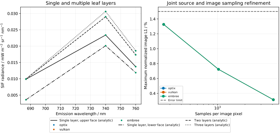
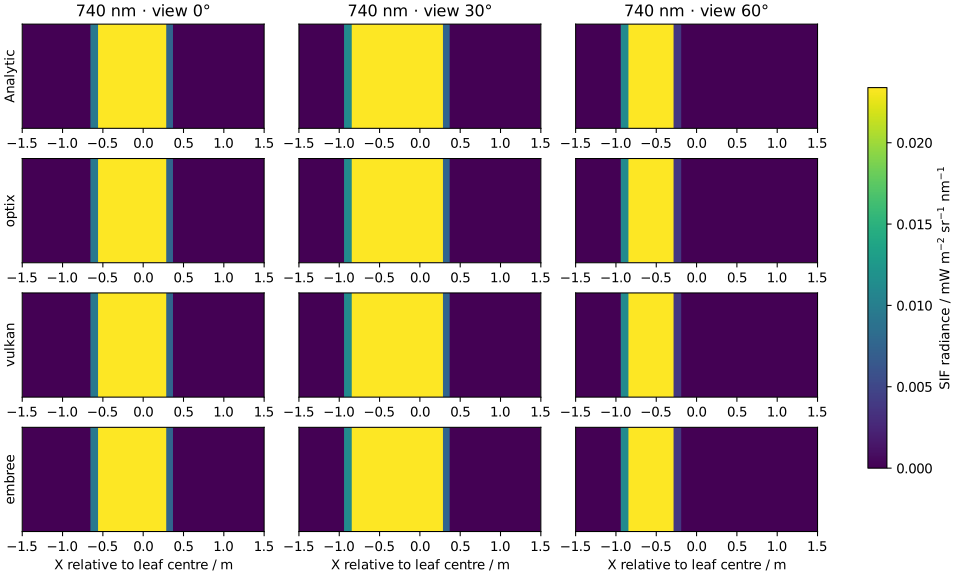
| Backend | Excitation error | Mean SIF error | Image L1 error | Final budget change | Result |
|---|---|---|---|---|---|
| optix | 0.0115% | 0.0622% | 0.3150% | 0.0451% | Pass |
| vulkan | 0.0115% | 0.0622% | 0.3150% | 0.0449% | Pass |
| embree | 0.0115% | 0.0622% | 0.3150% | 0.0451% | Pass |
All 36 results pass. All three backends return zero for zero yield and zero relative linearity error when the yield is doubled.
Absorbed-excitation error is normalized by the strongest absorbing leaf face in each band, with a 1% limit; this also evaluates analytically dark faces. Limits are 1% for each band's image-mean radiance and 1.5% for normalized image L1 error. L1 error is the sum of absolute differences across pixels and bands divided by the summed reference radiance. Each band's image mean must change by no more than 0.5% between the final two sampling levels. The zero-yield control uses an absolute limit of 10⁻¹⁰ W m⁻² sr⁻¹ nm⁻¹; doubled-yield relative linearity error must not exceed 10⁻⁵. Input and result files below provide individual checks.
Reproduce
- Inputs and sampling plan
- Fixed leaf coefficients
- Leaf mesh and slit panels
- Reproduction script
- Result data
Keep the relative script and data paths, then run:
Use --plot-only results/fluorescence/results.json to regenerate figures with matplotlib.